
The 1932 Morris Cowley Information Page
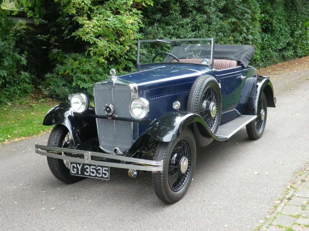
My 1932 Morris Cowley as it was in 1958 on the
left - pictured in Little Trevegean, Cornwall at location
50.106684, -5.686692 . It was then last
driven in 1965 and now restored - and sold on to a new owner nearly five years
ago, it is now back on the road!.
On the right is how it was in Sept 2014, having again moved under its own power at last on 04.09.14.
Click on
either of the images above for
a history of the car.
In almost all of this restoration I have been highly indebted to several persons
who have helped me considerably.
Mr Dave Ward of Caddington, Herts particularly; without whose skill and perseverance
throughout the majority of the work, I would
have got nowhere.
Also Radlett Classic Cars LLP and more recently,
Tony Almond
late of TA
Autos in Hemel Hempstead who
have all brought the restoration to its present condition.
Some pictures of the Restored car
|
On Thursday 4th
September 2014 the Cowley actually moved under its own power for the first
time since 1965!!! |
|
On Wednesday 22nd July 2015 the Cowley first went to Classics on
the Common in Harpenden, Herts. |
| Here can be found data and
information on: History
of the Car
|
II. Cowley up for
sale by Auction. Starting the engine and other information
14.02.14, 27.11.14, 09.02.15, 01.06.15, 01.07.16, 20.04.19, 18.01.24 |
Operation of the Four Position Ignition and Charging Switch - Lucas Type
"PLC" (that is to say the first version of
the Lucas PLC switch. Others are numbered PLC2-6)
This
particular
(and well used!) PLC switch controls three things:
- Ignition: On/off - using a spade ended key (later switches have key barrels)
- Charge: Low/High from the Dynamotor in summer/winter and when lights are on
- Lights: Switching between Off/Side/Head
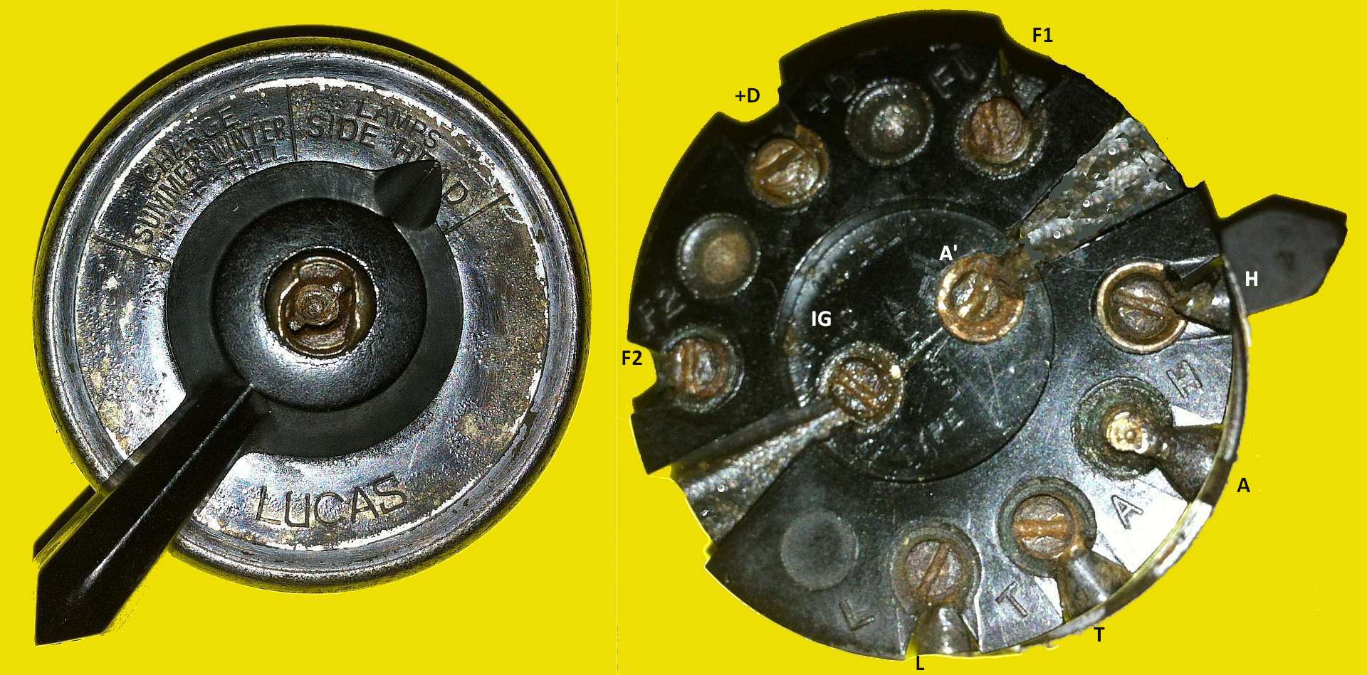
It has four settings: 'Charge Summer Half', 'Charge Winter Full', 'Lamps Side'
and 'Lamps Head'. The Ignition on/off switch is in the centre and is
operated by a spade key There are nine terminals on the rear: With one
exception these are labelled on the switch. The photo also indicates these.
They are: F2, +D, F1, IG, A', L, T, A and H.
NB(1): A' is actually not
labelled at all on the switch but is connected internally to A and is referred to as A' here.
It usually takes the input from the battery.
NB(2): There are blanked internal contacts between F2 and +D and between
+D and F1 - these are not terminals!
In operation, there is a coupling between charging and the use of lights so that more
charge is given by the Dynamotor when the lights are on.
If the PLC switch is in need of repair/restoration then there is an excellent
two-part article (courtesy of the Austin Seven Club)
here.
Remember NOT to prise off the three bent lugs that secure the rim and face
place. The rim is designed to be rotated to remove it.
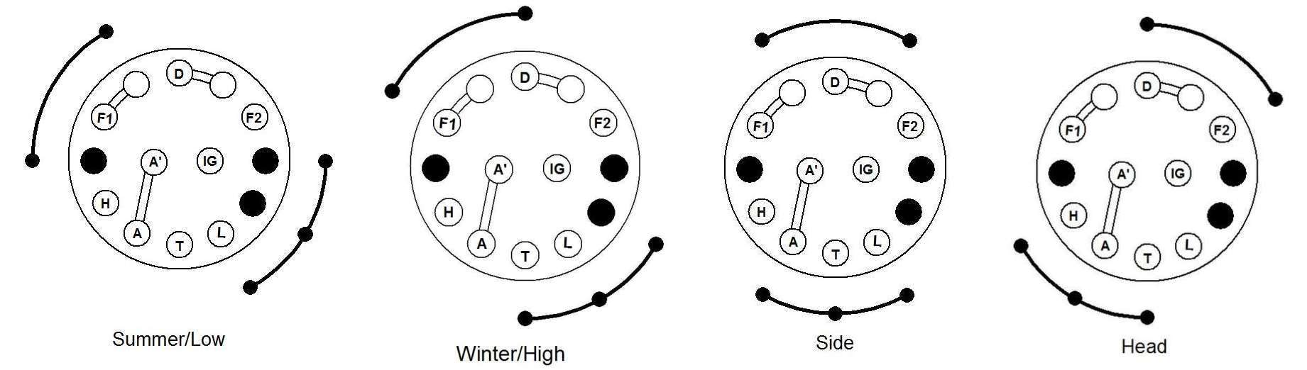
The following diagram illustrates what is connected to what for the various
settings of the four position PLC switch.
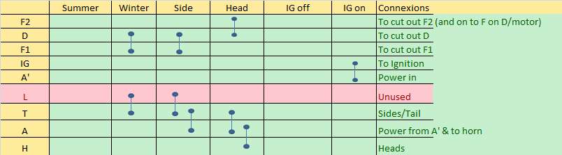
By way of further explanation, the diagram below indicates the
internal switch rotor settings for
each switch position as if 'seen' from the driver's perspective. The actual
connectors that may be seen on the back of the switch itself are of
course arranged in the other direction. The connexion pads on the rotor work by
interconnecting the pads with which they are in contact in the base of the
switch housing.
In the diagram below, the pads in the base that are connected to the car's wiring are lettered.
These correspond to the letters on the cut out (but see above re A').
Note: The pad lettered 'L' is not used at all on the Cowley, it being a relic
from the really early days of motoring.
See the explanatory note below.
Some of these 'base pads', like A', A, F1 and D, are connected internally by straps to other pads. The outer arcs in the diagrams below indicate diagrammatically the position of the switch's rotor-pads and its interconnecting contacts for both the charging and lighting positions. Thus for example in the 'Winter' setting D (connected to Generator output) is connected to F1. When headlights are employed D is connected to F2 and the power feed wired to A is connected to both Heads (H) and Side/Tail lights (T). When the ignition switch is turned on the power feed at A is fed via A' through to IG (the power feed to the coil ignition).
Explanation of Operation:
Charging Settings:
The D/F1/F2 connexions switch in, or short out, field resistors in the base of
the cut out as needed for
summer, winter and lights settings for charging.
These resistors were originally only located inside the Dynamotor but commonly ones
in the base of a later design of cut out (Lucas CFR2) have been used.
That is the position with my Morris Cowley. The Dynamotor on this car is a combined starter
and dynamo. It uses an adjustable third brush system to limit the
maximum
power output
when operating as a dynamo. The
actual output fed to the battery is
however further limited by the chosen strength of the field current; this being varied
by inserting
or removing resistors in the field circuit. Two of these resistors are
housed in the base of the CFR2 cut out.
Thus in summer and without lights (left above), no shorting out of the resistors leads to
higher field resistance and
therefore to the lowest charge rate.
In winter one of the resistors is shorted out leading to an increased charge
rate.
Winter charge rate also applies if the side lights are on - regardless of summer
or winter.
When head lights are on, no resistors are in the field circuit at all leading to the maximum
charge rate as set by the position of the third brush in the Dynamotor.
Ignition Settings:
Power from the battery always goes to A' (and also to A since the two are
internally connected) and thence to IG when the ignition key is turned to ON. It
is suggested my many that in any rewiring consideration should be given to
provide to A' only that power needed for the ignition and to wire directly to A
for all else. That way the current passing through the interconnecting
strap between A' and A in the switch is minimised.
Lighting Settings:
On Side setting, power from A goes to T for sides and tail lights
On Head setting power from A goes to both T (for sides/tail) and to H (for heads)
The L terminal has power to it in the Winter and side settings but this is not
used in the 1932 Morris Cowley. [In fact terminal L (Low) is very seldom used, being
originally incorporated for three lamp lighting sets where head/side lamps on
the wings carried bulbs with dim and bright filaments, the former acting as side
lamps].
Connecting a Lucas PLC Switch to a Lucas CFR2 Cut Out
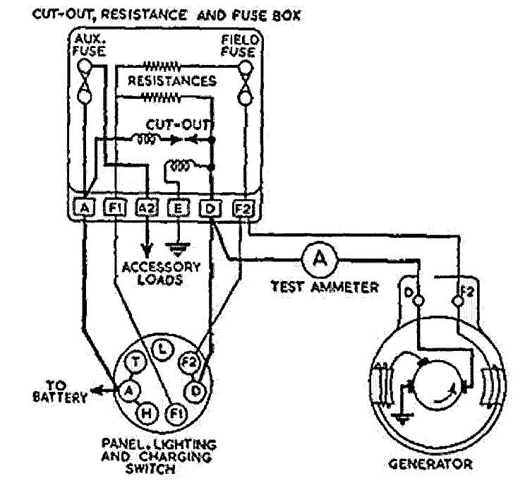
The connections from the switch and Dynamotor to the CFR2 Cut Out are as
shown.
NB(1) This does not show the centre Ignition switch connections of the PLC
Switch.
NB(2) The ammeter shown in the diagram is not the car's ammeter but is where one
should be placed in order to measure the output when adjusting the third brush.
See below for more on this.
Note that:
1. No 'in built' field resistors of the Dynamotor are used.
Those in the CFR2 are used instead.
2. With the engine not running, the cut-out contacts are open.
3. The ignition light on the car dashboard is effectively wired across the cut
out contacts.
4. When the ignition is turned on, terminal A of the PLC (battery +) is
connected to IG and then to one side of the Ignition warning light
5. The other connection of that light is connected to the +D terminal of the
PLC.
6. The ignition light is on.
7. As the engines speed increases the Dynamotor starts to generate and the voltage
on +D increases and the Ignition warning light fades.
8. The cut out closes when the dynamotor voltage exceeds that of the battery* and
the warning light goes out.
9. Terminal A of the CFR2 is connected to the Battery and is unfused at all times.
10. Terminal A2 is connected to the battery at all times but it is fused. This
is the main accessory power feed.
11. Side and tail lamp wires connect to T on the PLC
12. The head light wire connects to H on the PLC
* The cut out is there to prevent the battery from being discharged through the dynamotor at times when little or no current is being generated. The contacts of the cut out are spring loaded to stay open when the engine is off. The cut out has two electromagnetic coils. A 'shunt' wired coil, across terminals D&E, closes the contacts when the generator voltage has risen sufficiently to drive the necessary current through the coil. This action is factory set to occur when the dynamotor voltage is greater than the battery voltage. As soon as the contacts close the voltage across D&E immediately falls to that of the battery which by now is receiving a charging current. To prevent the contacts from opening again a second coil in series with the dynamotor uses the charging current to hold the contacts closed until such time as the engine slows (or is stopped) and the current through the series coil becomes insufficient to keep the contacts closed. At this point the contacts open again, the dynamotor voltage is by now insufficient to cause the shunt wired coil to close the contacts and the ignition light begins to glow again.
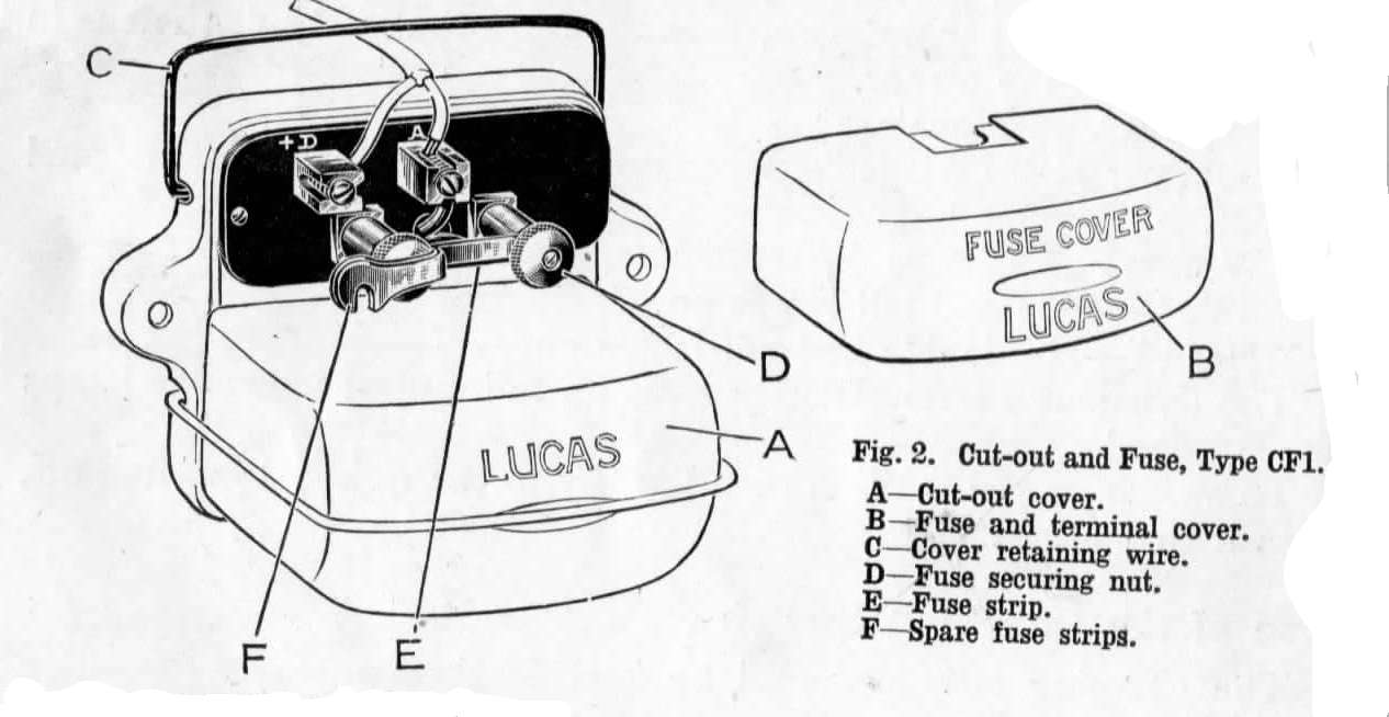
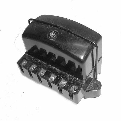
What Cut Out was supplied originally?
The 1932 Morris Cowley Cut Out as originally fitted was the Lucas CF1. In the original 1932 Cowley the lighting/charging switch together with the original Lucas CF1 two terminal (A and +D) form of cut out (see picture) offered only low and high output options for the dynamotor output; it had no inbuilt resistors (because there was one in the Dynamotor itself) and it therefore served only as a cut out. [Earlier Cowleys had a version of this cut-out but with a third terminal [earth] rather than just two because a chassis earth was not used on such cars]
The later user-modification on my car was to use the Lucas CFR2 cut out instead. It brought a slightly greater degree of control and more terminals for accessory loads. It also used the more modern glass cartridge fuses that are still available today. The CFR2 is still the one used on my Cowley as mentioned above.
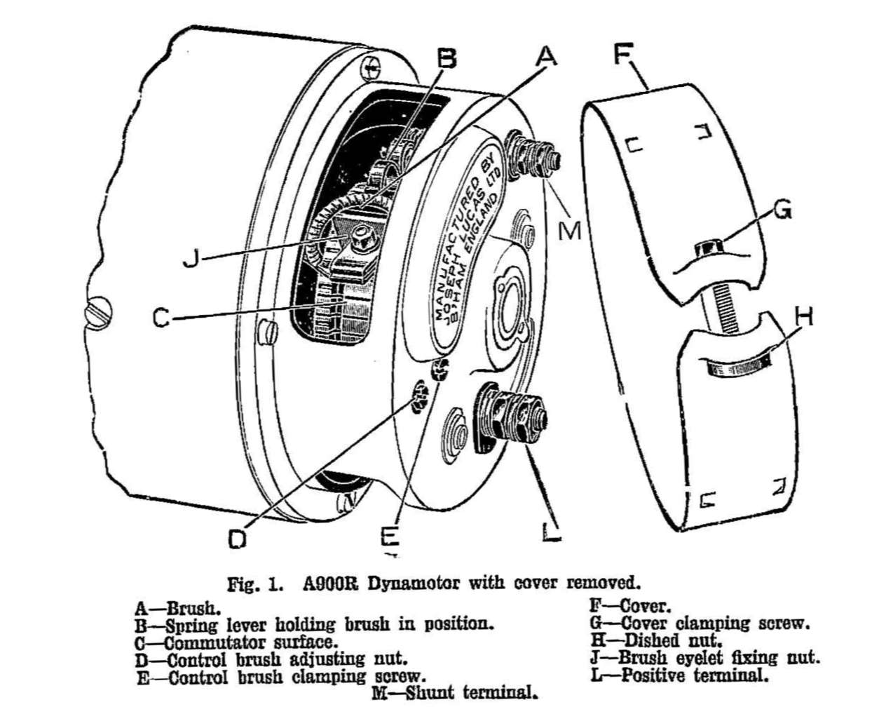
Operation of the Cowley 1932 Lucas A900R Dynamotor
 As fitted in 1932 the Lucas Dynamotor
was wired as in the wiring diagram below. Note
that the layout of the brushes shown in this diagram is viewed differently from
the more simplified diagram above. The 'black and yellow' wire from
the battery + terminal is the main electrical feed from the battery to the car.
It goes to one side of the dashboard ammeter. The 'yellow' wire from the
dynamotor D terminal is the main positive charging current output and it goes to
the cut out and thence to the battery through the car's ammeter. The
'green' wire from the dynamotor comes from the dynamotor F terminal and goes to
an F terminal on the cut out and thence to the lighting/charge PLC switch.
As fitted in 1932 the Lucas Dynamotor
was wired as in the wiring diagram below. Note
that the layout of the brushes shown in this diagram is viewed differently from
the more simplified diagram above. The 'black and yellow' wire from
the battery + terminal is the main electrical feed from the battery to the car.
It goes to one side of the dashboard ammeter. The 'yellow' wire from the
dynamotor D terminal is the main positive charging current output and it goes to
the cut out and thence to the battery through the car's ammeter. The
'green' wire from the dynamotor comes from the dynamotor F terminal and goes to
an F terminal on the cut out and thence to the lighting/charge PLC switch.
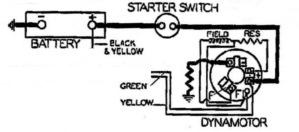
The Dynamotor has two field windings and three commutator brushes. It operates both as a starter motor and as a third brush dynamo. The first field winding is arranged to be in series with the armature output. This series connected field winding (shown as a zig-zag at the left of the dynamotor in the diagram and shown with 'thick' wiring) is the one used when the starter switch is pressed and the Dynamotor operates as a motor to start the engine. It will be recalled that series wound electric motors have enormous starting torque; as any late running commuter who has jumped onto a starting trolley bus will attest!
The second field winding is effectively placed across the dynamo output, that is to say it is a 'shunt' wound field coil. In fact it is connected between the (moveable) third brush and the positive output brush. This allows the position of the third brush to control the field current and so the maximum output current of the unit. A screw on the back of the unit allows the position of the third brush to be moved. As the third brush is moved toward the positive output brush (into the oncoming direction of rotation of the armature) the maximum available current from the dynamotor increases - and of course if it actually were to touch the positive output brush then a very high field current and very high output would be obtained - possibly one that exceeds the manufacturer's rating for the unit. Care is therefore needed in adjusting the third brush - which is why the use of a temporary ammeter in the circuit is shown above. As the brush is moved toward the negative (earthed) brush of the dynamotor then the maximum output of the dynamotor is reduced. Although it has disadvantages, this type of dynamo has the particular advantage that it gives a more or less constant charge rate despite considerable changes in speed of rotation, something that is very necessary as the car's engine speed changes.
It will be seen that a resistor is incorporated in the shunt field circuit (it is marked 'RES' on the diagram). In original models this may be located inside the dynamotor and serves to limit the field current and of course the unit's output. The point where this resistor is connected to the field coil (it is called a centre-tap) is brought out of the unit to the F terminal so that the resistor may be shorted out (and the dynamotor output may thereby be increased) when side or headlights are on and more power is needed.
As mentioned above there are some disadvantages of the third brush system. These became more apparent as changes in car design required greater use of electricity. The first is the lack of a properly flexible charging current. A three brush dynamotor will only charge at a few fixed rates. Each of these charge rates can of course be selected by the driver, but the available charge rate options may not coincide with the current state of the battery. Consequently one may see overcharging on long runs, and undercharging on short runs especially those runs having frequent starts and stops. Not only that but a three brush dynamotor with its more or less fixed 'top up rate' of charge can take a long time to recharge a completely exhausted battery. For these reasons third brush systems eventually came to be replaced by alternators with charging regulators. Nonetheless for the cars of the thirties the system was very reliable and broadly did its job. With such old classic cars now being used less frequently for modern motoring, the system remains ideal for them.
Cleaning the Commutator.
It is usual when cleaning the commutator of the Dynamotor to apply some fine
emery whilst the engine (and therefore the Dynamotor) is turned with the
starting handle and then to wipe the dust and grime so generated off with a
cloth wettened with petrol or methylated spirits. An alternative that has
been suggested to me (though not tried by me) and which might not wear the
commutator as much, is to use instead a rag soaked in T-Cut - the formula sold
for enhancing the colour of car bodywork. Of course you would still have to wipe
off the residue as above but this process might take off less copper whilst
achieving the same effect. I was offered this solution by a railway
modelling enthusiast since the commutators on model engine motors can be damaged
more easily if emery is used. I am assured that the result is excellent.
Please tell me if not!
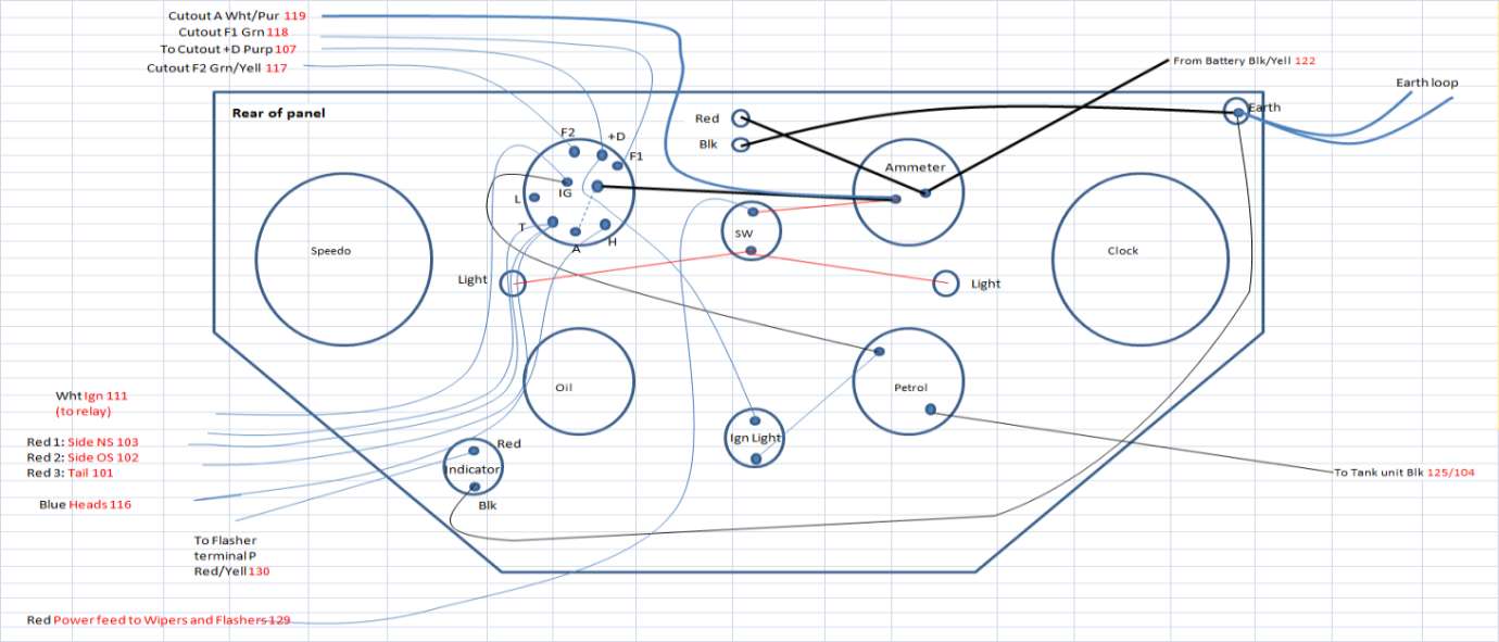
1932 Morris Cowley - Dashboard Rear Wiring
The diagram below shows the wiring as used on my car.
The flasher indicator at the bottom makes use of a hole that fifty years ago had
been drilled for a spot-light switch. The unidentified wire shown coming from
the ammeter side of the ignition switch was the original source of power for
this now unused spotlight and is no longer in use. The earth connexion
(top right) connects to an earth loop. This loop of wire was installed around
the car when it was rewired. This loop ensures that all mudguards are
properly earthed to the chassis and to the battery negative. The ignition
cable (shown as White with code 111) goes to power the coil ignition. A
relay is mentioned here only because it was necessary to permit use of a magneto
whilst the original coil ignition was being restored. For that use the normally
closed relay (a Durite 0-727-02) ensured that the magneto lead is earthed when
the ignition key is OFF and is open circuit when the ignition is ON. When
the coil ignition comes to be reinstated this relay will become redundant.
NB: This diagram shows only two connections to the petrol gauge - it
should be remembered that the case of this gauge needs to be earthed. The
connection to the ignition circuit is marked 'B' on the back of the gauge and
that to the tank 'T' on the back.
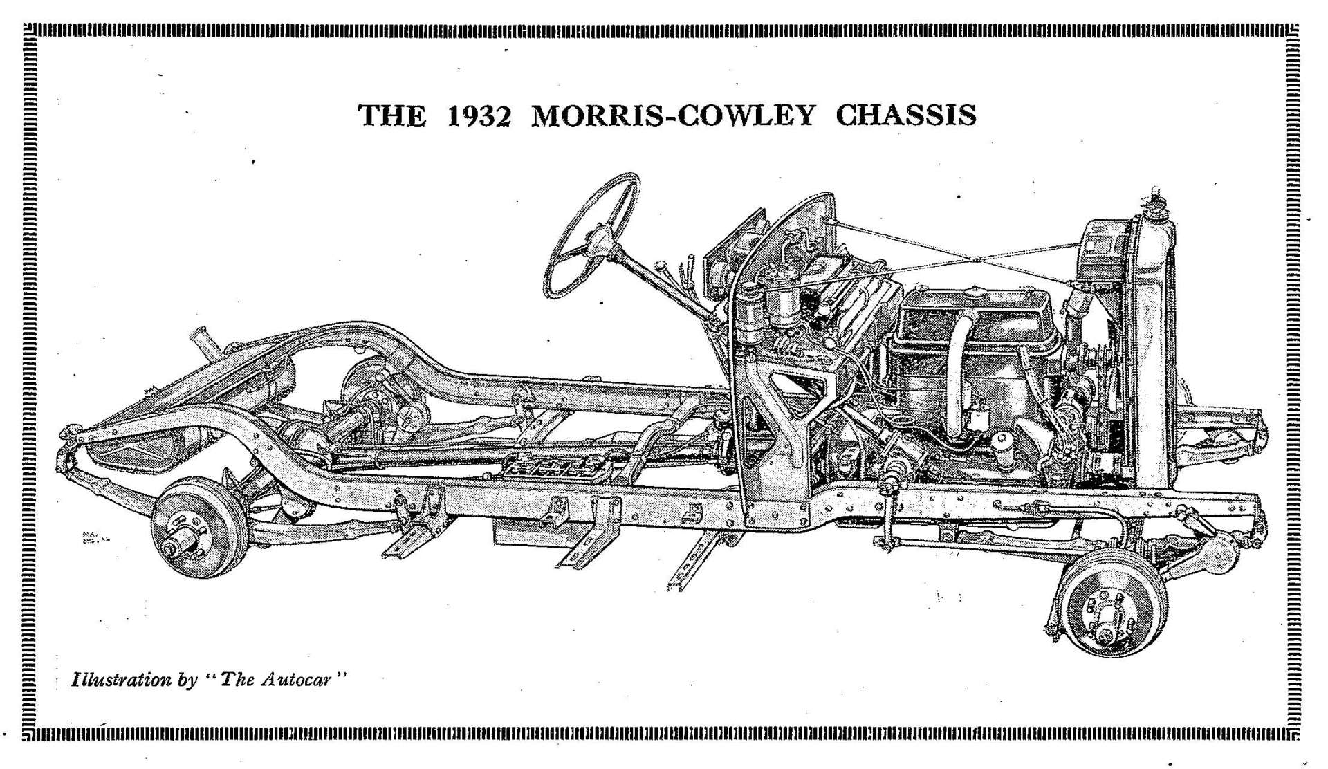
Drawing of Cowley Chassis from manual
Close up of Dashboard with some of the fittings identified...
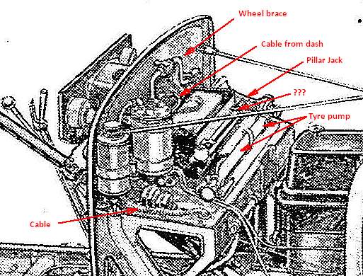
The item marked ??? on this diagram is actually the place for stowage of the starting handle!
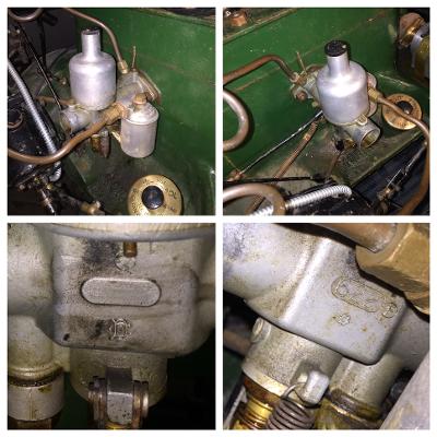
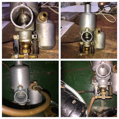
The Carburetter - Here are some images of the original SU carburetter taken before and after it was stripped down for cleaning and reassembly in order to establish a possible cause of difficulty in starting. It was then thought that this was a sensible move since the carburetter had NEVER been cleaned during my entire ownership until then (some 40 years at that point (!)). The images show just how filthy the carburettor had become by then and I had to purchase an ultrasonic cleaning bath to do it properly. I would really recommend such a purchase - as can be seen it did a wonderful job. However it has also to be said that it made no difference whatsoever to the then starting problem! Such is the excellent engineering of SU Carburetters I suppose.
The Brake Cylinder - here are three views of the component parts of the 1932 Cowley Brake Master Cylinder
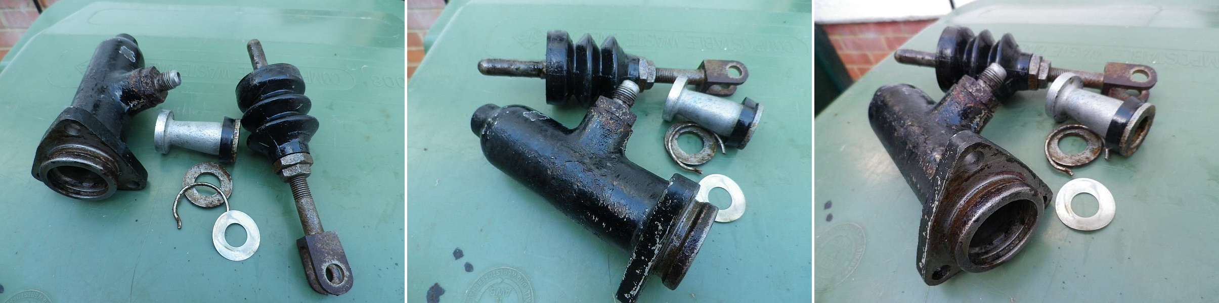
Sometimes corrosion-pitting occurs in the master cylinder bore. This
can allow brake fluid to leak past the piston. Although re-sleeving of the
bore is clearly the best solution to this problem,
a quite acceptable solution may in some circumstances* be achieved by degreasing
the entire housing and filling the pitting using a metallic-impregnated epoxy
resin such as
JB Weld.
Simple sanding using fine emery cloth before the repair has completely set is then all that is needed to obtain a
completely smooth bore.
* NB The owner must decide for him/herself whether in their particular circumstances such a solution is appropriate or not. No responsibility is accepted for others' use of this approach.
![]() Ignition
timing - single handed!
Ignition
timing - single handed!
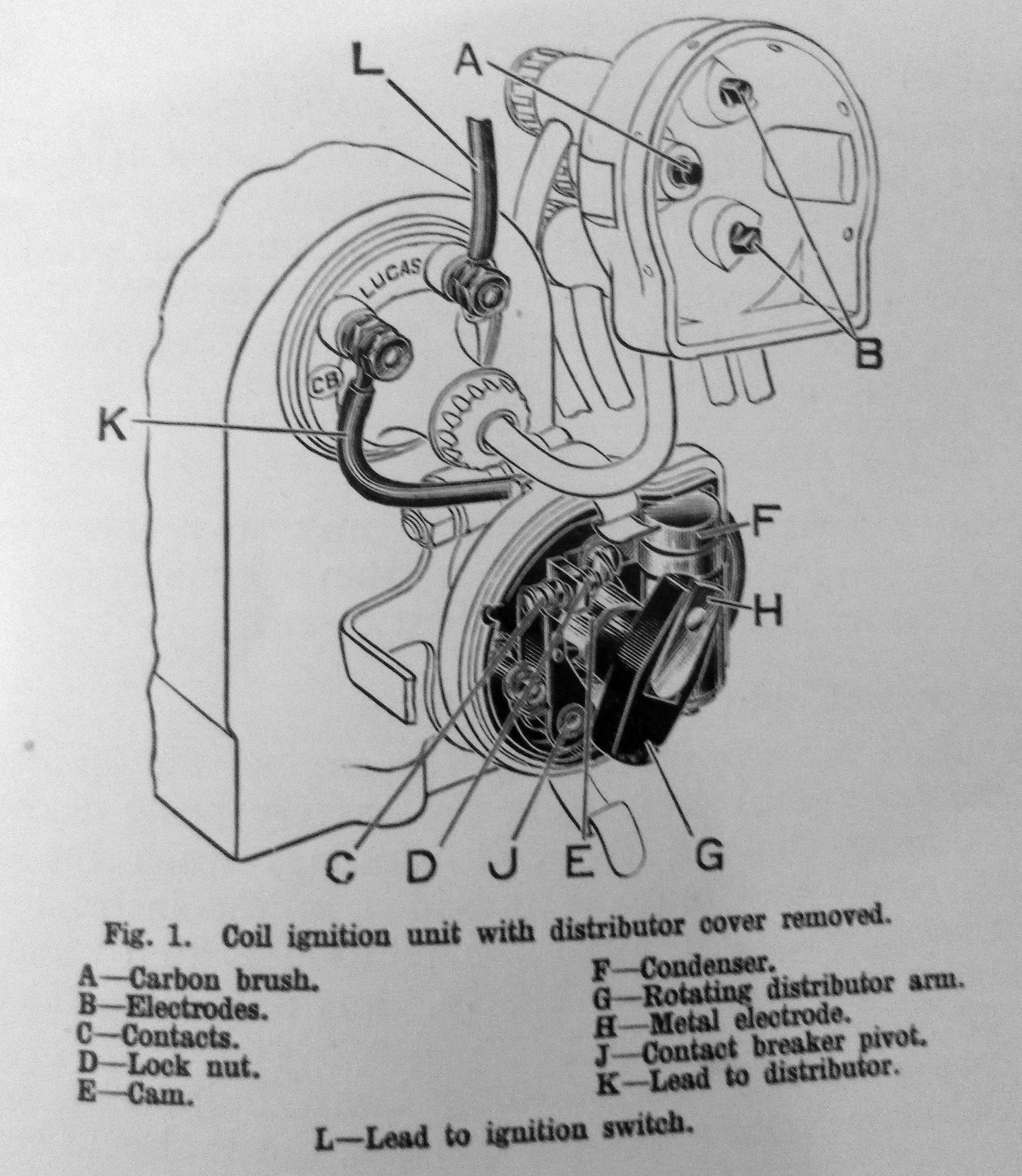
The 1932 model of the Morris Cowley operated a rudimentary form of coil ignition which used the earlier years' magneto-mounting and a distributor which required manual adjustment of Advance and Retard of the ignition; Fully retarded for starting (and occasionally on hills) and a modest advance for ordinary running. There is a little more about the vagaries of this system here.
However things are not always as easy as they seem. Firstly the 1932 Cowley Operation Manual is a little confusing! It says on p18 that the engine valve timing is to be set so that No 1 cylinder is just firing when the inlet valve of No 4 cylinder is just opening with the spark fully retarded. But then it also says on p10 that the Adv/Ret control should be set mid way to start the engine. The important thing is that the cylinders cannot fire before TDC however retarded the control is set.
Setting the ignition timing is straightforward. With the manual advance/retard set to fully retarded and the ignition points gap in the distributor correctly set using a gauge supplied with the ignition spanner, (or 0".016 if a Bosch replacement 009 distributor is being used) the points should be set to be just opening at Top Dead Centre (TDC) on the Compression stroke of any cylinder. This is most easily done by using No1 Cylinder (that nearest the radiator) and the engine turned until the rotor arm of the distributor is pointing to the spark plug lead for No1 cylinder. When cylinder No1 is at the top of its compression stroke that of No4 cylinder (counting from the radiator) is at the top of its exhaust stroke. The Cowley cylinder head has a small plug near No4 spark plug which can be removed using a spanner and a rod (a drinking straw is ideal since it will slide easily and stay in place in the hole!) placed in there to detect the maximum excursion of No4 cylinder. What is less easily found when turning the starting handle - especially if this is being done single handed after complete removal of the ignition system for any purpose - is whether the movement of the straw coincides with the exhaust or compression stroke. An easy way to determine this is to remove all spark plugs, something which in any case makes for smoother turning of the starting handle, then to part-replace the plug in No1 cylinder. This has the effect of generating a hiss when No1 cylinder approaches compression.
***Remember that any adjustment to the points gap also affects the timing of the spark so the best procedure is as follows.
At this point (if needed) the carburetter may be adjusted according to the instructions on p56 of the 1932 Operating Manual.
Having trouble finding Hubcap securing nuts? Try here.
Have a look at some of the super cars that did make it to the 2013 Kop Hill Climb Here. Sadly we could get there that year, but we did go in 2015 and 2016. We went again in 2018!!
An amusing account of early Morris Motoring! - How far we have come!!
[Cowley History] [Hub Cap securing nuts] [Door and Lock fitting] [Kop Hill Climb 2013] [Home]
© P.Powers 2012, 2013, 2015, 2016, 2017, 2018
 I - An
Interesting Question about the 1932 Cowley's distributor... and the answer!
I - An
Interesting Question about the 1932 Cowley's distributor... and the answer!