The Fuel Gauge and Tank Unit
How it works
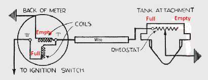
Diagnosing fuel gauge problems is best done by following the instructions given on the Cornwall Austin Seven Website. This shows an excellent fault finding diagram and it gives an explanation for the way the gauge operates. That diagram is reproduced below with some added explanations by me in red:
The fuel gauge is what is called a double coil moving-iron meter. There are three electrical connexions to such a fuel gauge: Terminal 'B' (connected to the ignition switch and battery positive), Terminal 'T' (which is connected to the Tank Unit) and the gauge case itself (which is unmarked but is earthed to battery negative). The unit at the petrol tank is housed in a flameproof chamber secured by six screws into the top of the fuel tank.
[Information: Most electrical gauges work by some or all or the current in a circuit passing through a coil of wire positioned near a magnet and the coil's subsequent deflexion being controlled by a hair spring. A needle mounted on the coil shows the extent of deflexion. That way more current means more power and more deflexion of the needle. Moving iron meters do not use a magnet, instead they depend on the pull of the magnetism in the coil on a piece of iron which may be shaped to permit the surrounding air to dampen its movement and that of the attached needle. Moving iron meters are especially useful in that they may be used with both direct and alternating current. Double coil moving iron meters use a second coil instead of a controlling spring. The different currents flowing in the two coils controls the needle's deflection. Some later meters of this type have more than two coils - the additional ones being in parallel with the main ones. This configuration permits adjustment and calibration of the meter.]
The two coils in the gauge work as follows: The coil marked 'Full' (in red in the diagram above) drives the meter needle towards the full mark whilst the coil marked 'Empty' reverses that. Left to itself, without the tank unit connected, the gauge is equally affected by both coils and therefore the needle does not move and the gauge shows empty. With the tank unit connected and the tank full of fuel, the 'Empty' coil of the gauge is short circuited and so the meter reads full. With the tank empty the full resistance of the tank unit rheostat is across the empty coil which is therefore not shorted out and the meter falls back to show empty. The resistance wire is connected to the 'T' terminal of the gauge at one end and after being wrapped around the slider pivot to keep it in place, it is connected to earth at the other (not shown in the diagram above but visible in the right hand image of my gauge below.).
The resistance of my sender unit is hard to measure properly but it appears to vary between zero (tank full) and 160 ohms (tank empty) with a useable highest tank empty value of just over 140 ohms.
Advantages and Disadvantages of the Moving Iron Gauge
An advantage of the twin coil moving iron fuel gauge is that it is less affected by changes in battery voltage, for example when the engine is idling or when the lights are on. A problem with the combination of a moving iron type of fuel gauge and its tank unit is that the reading can be affected as fuel moves in the tank during cornering, on hills or when braking. It is to minimise this effect that, on the Morris Cowley, the sender unit is mounted in the centre of the tank.
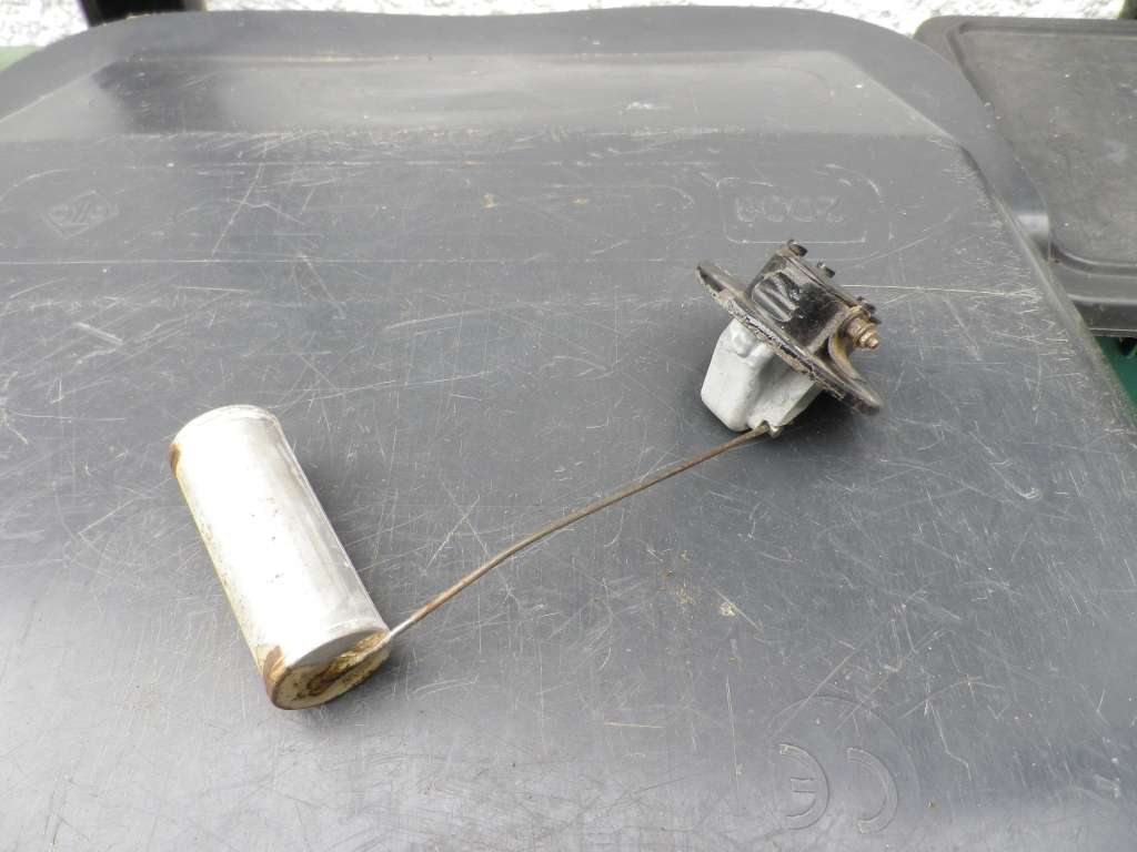
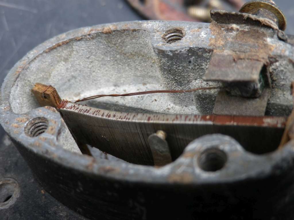
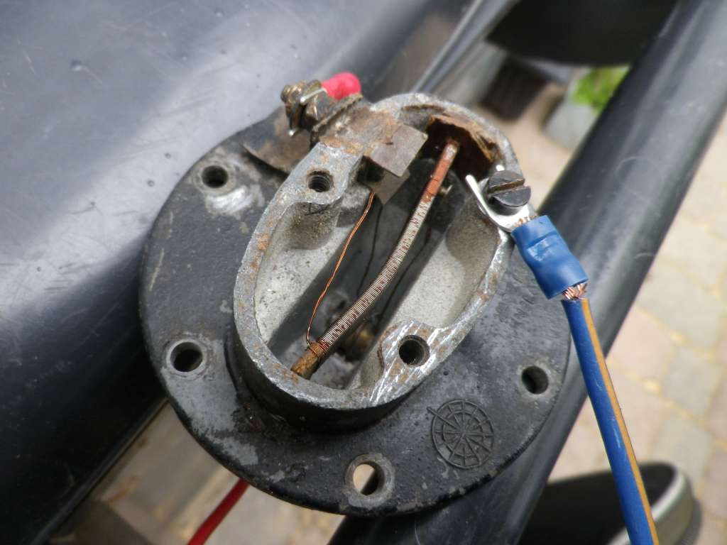
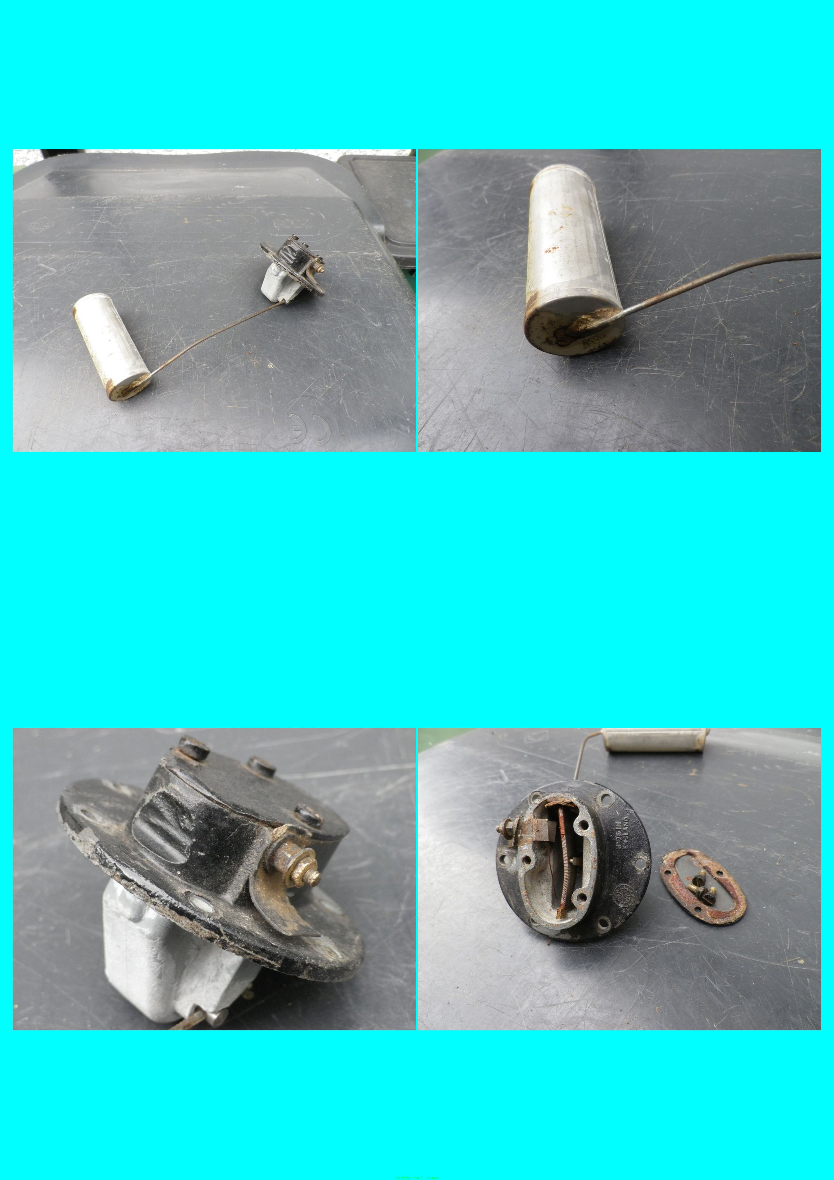
Photographs of the tank unit. Note the use of a twin thickness wire between the left hand end of the resistor and the insulated terminal to prevent its resistance affecting the reading. The other end of the resistor (see the image on the right) uses only one thickness of wire which is looped around the slider pivot before going up to be earthed to the tank unit case behind the insulated terminal and held in place by it. In my gauge this connexion seems to be open circuit though that does not prevent operation and the risk of doing damage during a possible repair, outweighs any attempt to fix it.
Sorting out the problem with my Gauge and Tank Unit
In the case of my car and after using the excellent Austin Seven test, the problem was quickly found to be the tank unit. When this was removed it was clear that the float was sticking to the point of being jammed. This appears to have been a result of the unit being left fitted to the tank when the white fuel-tank-sealer was sloshed around by the company who did some early restoration. Close up images of my Cowley's fuel gauge
A little careful cleaning with a brass brush and some lubrication of the slider pivot solved that problem. However even after that had been freed, it still did not work 'electrically'. The slider did not seem to make sufficient contact with the resistance wire and it seems that the rheostat wire itself may have become slightly oxidised. Some folded 1200 grit emery paper was carefully used between the two and the pressure of the slider on the resistance wire was increased a little (by bending it inwards!). In all of this testing an electrical test-meter had been used to measure the resistance as the float was moved up and down and it's worth mentioning that there was a point where the test meter still showed things as erratic yet a temporary connexion to the 12volt system of the car and to the dashboard gauge (conducted well away from the tank!) showed that it was indeed working rather better than that. I think the low voltage of the test meter was unable to overcome whatever oxidation still remained on the resistance wire and the slider contact. Moral: Don't assume too soon that the tank unit is useless!
A little more sanding left the gauge working passably well. It is still not completely smooth in operation over all its range - but hey, it is 80+ years old and it is still original. If however a replacement tank unit proves to be necessary in any other restoration, they are available from Internet based companies like Holden's - though the replacement's resistance may not be quite the same as the one it is replacing. Search the site for 'sender'.
Finally, a test of the float in some hot water showed no air bubbles - and hence no holes that might have needed soldering. The unit was restored to the car with new neoprene gaskets.
[Information: Why does the moving arm in the fuel sender not cause an explosion from sparking as it moves within such proximity to the petrol in the tank? The answer lies both in the design of the rheostat and that of of the sender unit case. First of all the tungsten 'pip' on the end of the slider overlaps more than one turn of the resistance winding. It is therefore always in contact at some point and the voltage difference between adjacent turns is insufficient to cause a spark. In the rare event that that mechanism might fail and a spark were to be generated, the casing of the unit is made to be sufficiently bulky and the airspace inside sufficiently small to ensure that its thermal capacity is huge and any fire/explosion will be contained without the exterior temperature of the casing rising to anything like the point where it could cause petrol to ignite. Finally the connexion between the external float and the internal slider is made sufficiently tight, tortuous and bulky that it acts as a 'flame arrester' (in the same way that the Davy Safety lamp works for gases like methane). Thus, any flame that might just possibly arise inside the unit is quickly cooled to the point of extinction and is prevented by the flame arrester design from causing any problem outside the unit.
26/09/2022