Double Dip Headlight Conversion
All cars need to have double-dip headlights these days. The Morris Cowley was originally made to use 'Dip and Switch' where upon operating the dip switch (located on the centre boss of the steering column) the nearside reflector was pulled sideways and downwards by a solenoid and that action also disconnected the offside headlight. The reflectors may be removed from the headlamp casing by removing the single brass screw that is under the cork (or neoprene) weatherproofing gasket and then rotating the loosened reflector clockwise by about 30 degrees to bring its securing flanges in line with the access recesses in the headlamp casing. They may be refitted by reversing this procedure.
The Cowley headlight reflectors each have a central hole and a clamping mechanism at the rear which secures the bulb holder in place. The original style holder took a single contact 12v 36w bulb and the focus of the beam was adjusted by pulling out or pushing in this cylindrical holder before clamping it in place. Once in the right place it was secured in position by the screw circlip.
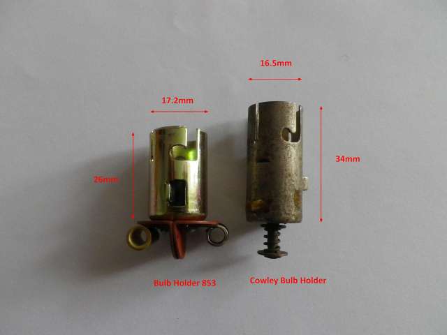
The left picture shows the original Cowley bulb holder design (on the right) and the double dip conversion holder on the left. The double dip one shown here can be obtained from Vintage Car Parts. Despite a small difference in diameter it still fits into the lamp reflector.
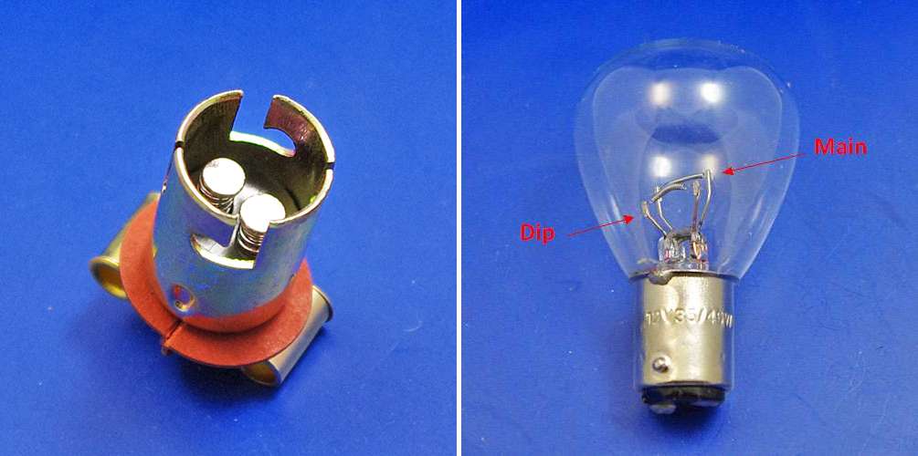
In a conventional double dip conversion a double filament bulb is used and this has two contacts on its base and of course the metal cap is earthed. Most easily-available 36w/36w bulbs seem to be made with parallel pins - that is to say they can be inserted into their holder either way round. Accordingly one might prefer to use a parallel pin rather an offset pin holder. However offset pin holders and bulbs are available. Designs change and some holders now have twin screw pillars instead of the push in wiring system shown here.
The second image shows more detail of the conversion system.
The dip switch at the steering wheel actually earths the wire
leading to it. Because it is difficult to thread modern thick wiring down
the central tube of the steering column a thinner wire and a relay is best used
instead. The relay can be housed inside the nearside headlight without the
need to interfere with the original reflector mechanism. A Durite Changeover
relay: 0-728-13 with an inbuilt diode works well.
However, there is a need to remember the diode polarity when wiring this
up. See the diagram below. Pin 86 must be the positive feed.
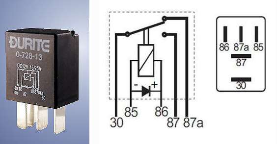
The pin numbering is:
30 Power when Heads switched on. Connected to 86.
85 To Dip Switch. Earthed when dip set.
86 Positive power feed to relay when Heads are switched on. Connected to 30.
87 Dip Beam power feed to NS and OS dipped filaments
87a NS & OS Heads Main Beam power feed. Connects to NS and OS main filaments
The bulbs in their holders should be set into the reflectors in such a way that the filaments are horizontal and with the dip filament below the main one.
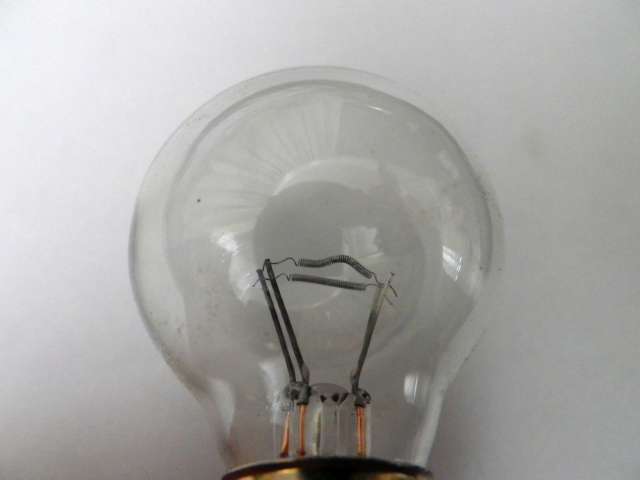
NOTE: The twin contact 36w/36w bulbs are not cheap to buy yet frequently the quality is variable. It is important to choose bulbs where the filaments are straight and horizontal and not sagging otherwise a distorted beam will result. An example of a bulb where the dipped filament is inadequate can be seen below: